8.12.1. Capacitor Inductor
#r# This example shows the simulation of a capacitor and an inductor.
#r#
#r# To go further, you can read these pages on Wikipedia: `RC circuit <https://en.wikipedia.org/wiki/RC_circuit>`_
#r# and `RL circuit <https://en.wikipedia.org/wiki/RL_circuit>`_.
####################################################################################################
import numpy as np
import matplotlib.pyplot as plt
####################################################################################################
import PySpice.Logging.Logging as Logging
logger = Logging.setup_logging()
####################################################################################################
from PySpice.Probe.Plot import plot
from PySpice.Spice.Netlist import Circuit
from PySpice.Unit import *
from scipy.optimize import curve_fit
####################################################################################################
# Warning: the capacitor/inductor return current in the generator
# could use switches instead
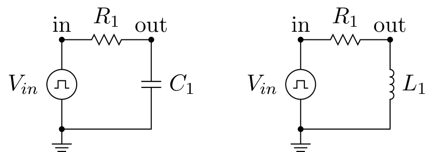
#r# We will use a simple circuit where both capacitor and inductor are driven by a pulse source
#r# through a limiting current resistor.
#f# circuit_macros('capacitor_and_inductor.m4')
# Fixme: for loop makes difficult to intermix code and text !
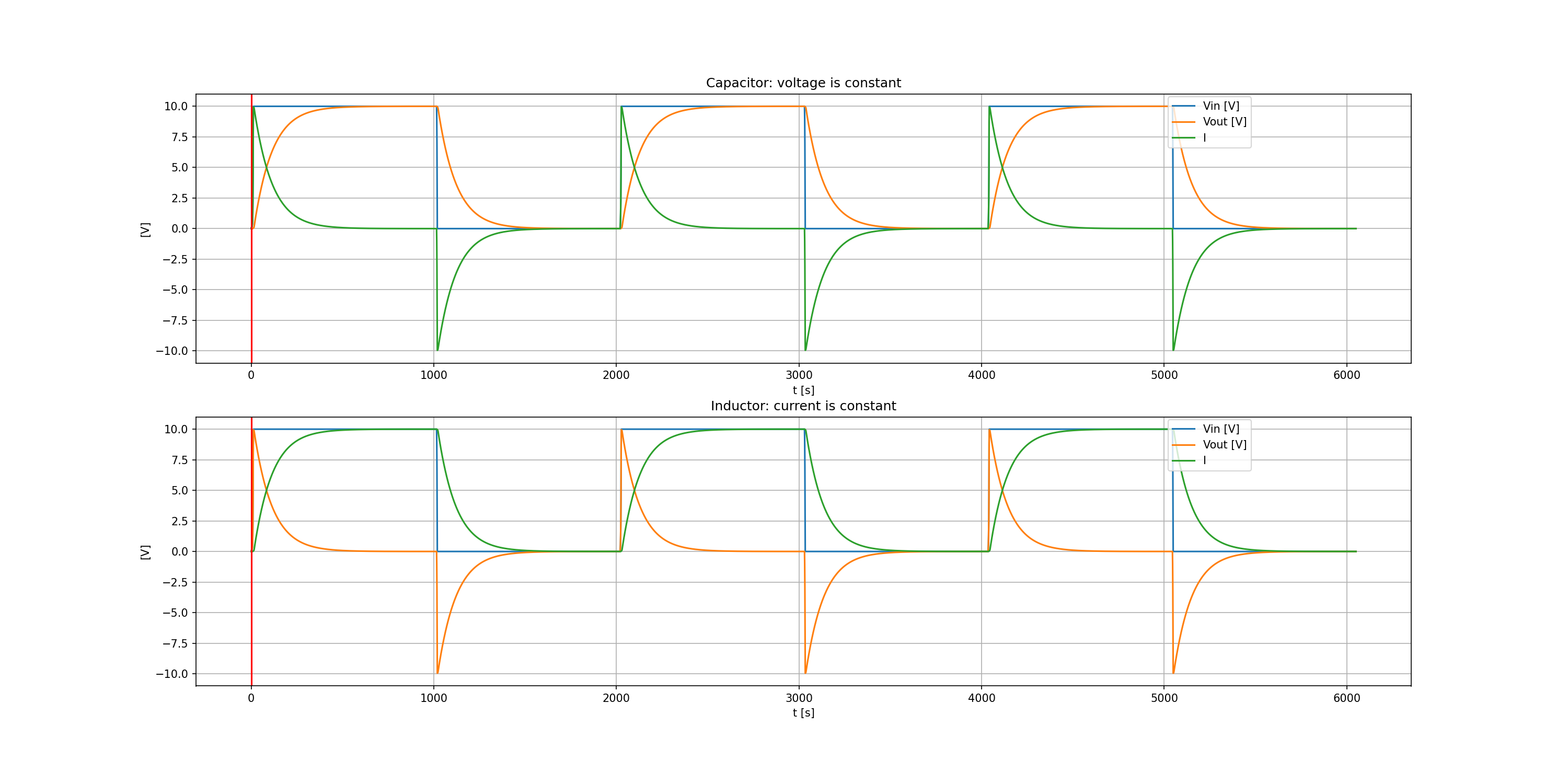
#r# We will fit from the simulation output the time constant of each circuit and compare it to the
#r# theoretical value.
figure, (ax1, ax2) = plt.subplots(2, figsize=(20, 10))
element_types = ('capacitor', 'inductor')
for element_type in ('capacitor', 'inductor'):
circuit = Circuit(element_type.title())
# Fixme: compute value
source = circuit.PulseVoltageSource('input', 'in', circuit.gnd,
initial_value=0@u_V, pulsed_value=10@u_V,
pulse_width=10@u_ms, period=20@u_ms)
circuit.R(1, 'in', 'out', 1@u_kΩ)
if element_type == 'capacitor':
element = circuit.C
value = 1@u_uF
# tau = RC = 1 ms
else:
element = circuit.L
# Fixme: force component value to an Unit instance ?
value = 1@u_H
# tau = L/R = 1 ms
element(1, 'out', circuit.gnd, value)
# circuit.R(2, 'out', circuit.gnd, kilo(1)) # for debug
if element_type == 'capacitor':
tau = circuit['R1'].resistance * circuit['C1'].capacitance
else:
tau = circuit['L1'].inductance / circuit['R1'].resistance
simulator = circuit.simulator(temperature=25, nominal_temperature=25)
step_time = 10@u_us
analysis = simulator.transient(step_time=step_time, end_time=source.period*3)
# Let define the theoretical output voltage.
if element_type == 'capacitor':
def out_voltage(t, tau):
# Fixme: TypeError: only length-1 arrays can be converted to Python scalars
return float(source.pulsed_value) * (1 - np.exp(-t / tau))
else:
def out_voltage(t, tau):
return float(source.pulsed_value) * np.exp(-t / tau)
# Fixme: get step_time from analysis
# At t = 5 tau, each circuit has nearly reached it steady state.
i_max = int(5 * tau / float(step_time))
popt, pcov = curve_fit(out_voltage, analysis.out.abscissa[:i_max], analysis.out[:i_max])
tau_measured = popt[0]
# Fixme: use Unit().canonise()
print('tau {0} = {1}'.format(element_type, tau.canonise().str_space()))
print('tau measured {0} = {1:.1f} ms'.format(element_type, tau_measured * 1000))
if element_type == 'capacitor':
ax = ax1
title = "Capacitor: voltage is constant"
else:
ax = ax2
title = "Inductor: current is constant"
ax.set_title(title)
ax.grid()
current_scale = 1000
ax.plot(analysis['in'])
ax.plot(analysis['out'])
# Fixme: resistor current, scale
ax.plot(((analysis['in'] - analysis.out)/circuit['R1'].resistance) * current_scale)
ax.axvline(x=float(tau), color='red')
ax.set_ylim(-11, 11)
ax.set_xlabel('t [s]')
ax.set_ylabel('[V]')
ax.legend(('Vin [V]', 'Vout [V]', 'I'), loc=(.8,.8))
#o#
plt.tight_layout()
plt.show()
#f# save_figure('figure', 'capacitor-inductor.png')
# Fixme: Add formulae
This example shows the simulation of a capacitor and an inductor.
To go further, you can read these pages on Wikipedia: RC circuit and RL circuit.
import numpy as np
import matplotlib.pyplot as plt


import PySpice.Logging.Logging as Logging
logger = Logging.setup_logging()


from PySpice.Probe.Plot import plot
from PySpice.Spice.Netlist import Circuit
from PySpice.Unit import *

from scipy.optimize import curve_fit


# Warning: the capacitor/inductor return current in the generator
#  could use switches instead
We will use a simple circuit where both capacitor and inductor are driven by a pulse source through a limiting current resistor.
# Fixme: for loop makes difficult to intermix code and text !
We will fit from the simulation output the time constant of each circuit and compare it to the theoretical value.
figure, (ax1, ax2) = plt.subplots(2, figsize=(20, 10))

element_types = ('capacitor', 'inductor')

for element_type in ('capacitor', 'inductor'):

    circuit = Circuit(element_type.title())
    # Fixme: compute value
    source = circuit.PulseVoltageSource('input', 'in', circuit.gnd,
                           initial_value=0@u_V, pulsed_value=10@u_V,
                           pulse_width=10@u_ms, period=20@u_ms)
    circuit.R(1, 'in', 'out', 1@u_kΩ)
    if element_type == 'capacitor':
        element = circuit.C
        value = 1@u_uF
        # tau = RC = 1 ms
    else:
        element = circuit.L
        # Fixme: force component value to an Unit instance ?
        value = 1@u_H
        # tau = L/R = 1 ms
    element(1, 'out', circuit.gnd, value)
    # circuit.R(2, 'out', circuit.gnd, kilo(1)) # for debug

    if element_type == 'capacitor':
        tau = circuit['R1'].resistance * circuit['C1'].capacitance
    else:
        tau = circuit['L1'].inductance / circuit['R1'].resistance

    simulator = circuit.simulator(temperature=25, nominal_temperature=25)
    step_time = 10@u_us
    analysis = simulator.transient(step_time=step_time, end_time=source.period*3)

    # Let define the theoretical output voltage.
    if element_type == 'capacitor':
        def out_voltage(t, tau):
            # Fixme: TypeError: only length-1 arrays can be converted to Python scalars
            return float(source.pulsed_value) * (1 -  np.exp(-t / tau))
    else:
        def out_voltage(t, tau):
            return float(source.pulsed_value) * np.exp(-t / tau)
    # Fixme: get step_time from analysis
    # At t = 5 tau, each circuit has nearly reached it steady state.
    i_max = int(5 * tau / float(step_time))
    popt, pcov = curve_fit(out_voltage, analysis.out.abscissa[:i_max], analysis.out[:i_max])
    tau_measured = popt[0]

    # Fixme: use Unit().canonise()
    print('tau {0} = {1}'.format(element_type, tau.canonise().str_space()))
    print('tau measured {0} = {1:.1f} ms'.format(element_type, tau_measured * 1000))

    if element_type == 'capacitor':
        ax = ax1
        title = "Capacitor: voltage is constant"
    else:
        ax = ax2
        title = "Inductor: current is constant"
    ax.set_title(title)
    ax.grid()
    current_scale = 1000
    ax.plot(analysis['in'])
    ax.plot(analysis['out'])
    # Fixme: resistor current, scale
    ax.plot(((analysis['in'] - analysis.out)/circuit['R1'].resistance) * current_scale)
    ax.axvline(x=float(tau), color='red')
    ax.set_ylim(-11, 11)
    ax.set_xlabel('t [s]')
    ax.set_ylabel('[V]')
    ax.legend(('Vin [V]', 'Vout [V]', 'I'), loc=(.8,.8))
tau capacitor = 1.0 ms
tau measured capacitor = 1.0 ms
tau inductor = 1.0 ms
tau measured inductor = 1.0 ms
plt.tight_layout()
plt.show()
# Fixme: Add formulae